TNC SERIES ( 50ohm 0-11 GHz / 75 ohm 0-1GHz)
TNC series features screw threads for mating. Threaded coupling interface ensures connector will not de-couple in vibration-intensive applications.
Our TNC connectors are with constant 50Ω and 75 Ω impedances, and operate from 0 - 11 GHz. TNC connectors are primarily used to antennas, base station, cellular, network, radar, telecom…etc.
Reverse Polarity TNC is also available.
| |
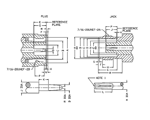
TNC-PLUG |
|
TNC-JACK |
| |
Min |
Max |
|
Min |
Max |
| A |
11.18 |
|
A |
9.60 |
9.70 |
| B |
Flared to Meet Good Electrical Contact |
B |
8.79 |
9.04 |
| C |
4.83 |
- |
C |
8.31 |
8.46 |
| D |
1.32 |
1.37 |
D |
8.10 |
8.15 |
| E |
5.33 |
5.84 |
E |
- |
4.72 |
| F |
0.15 |
0.46 |
F |
1.73 |
2.24 |
| G |
5.28 |
5.79 |
G |
8.31 |
8.51 |
| H |
0.08 |
1.02 |
H |
4.75 |
- |
| J |
2.06 |
2.21 |
J |
4.72 |
5.23 |
| K |
1.98 |
- |
K |
- |
0.15 |
| M |
- |
1.98 |
L |
4.95 |
- |
| N |
1.60 |
- |
M |
2.06 |
2.21 |
| P |
3.96 |
- |
N |
- |
6.50 |
| R |
- |
0.64 |
P |
4.78 |
5.28 |
| |
|
|
R |
10.52 |
- |
| |
|
|
S |
0.38 |
0.76 |
NOTE 1 : I.D. TO MEET VSWR AND CONTACT RESISTANCE
WHEN MATED WITH 1.32/1.37 MM DIA. PIN.
|
Material |
|
Part Name |
Material |
Finish |
|
Bodies |
Brass |
Nickel, Mirraloy…
( per requirement) |
|
Center Contacts
|
Male: Brass |
Gold, Nickel…
(per requirement)
|
|
Female: Brass, Phosphor Bronze,
Beryllium Copper |
|
Insulators |
Teflon, Delrin, PBT |
None |
|
Gaskets |
Rubber, Silicone Rubber |
None |
|
Ferrules |
Annealed copper |
Same as Body |
|
Electrical Data |
|
Impedance |
50Ω |
75Ω |
|
Frequency Range |
0~11 GHz |
0-1 GHz |
|
RF-Leakage
–connector for flexible cables
–connector for semi-rigid cables |
( ≥ 60 dB) |
( ≥ 60 dB) |
|
Dielectric Withstanding Voltage
( at sea level ) |
1.5K Vrms, 50Hz
(depending on cable) |
1.5K Vrms, 50 Hz
(depending on cable) |
|
Working Voltage (at sea level) |
500 Vrms,50Hz |
500 Vrms,50Hz |
|
≤ 500 Vrms, 50Hz
(depending on cable) |
≤ 500 Vrms, 50Hz
(depending on cable) |
|
Insulation resistance |
5.103 Ω |
5.103 Ω |
|
Contact resistance |
|
- center contact |
3 MΩ ( ≤1.5MΩ) |
3 MΩ ( ≤1.5 MΩ) |
|
- outer contact |
2 MΩ ( ≤ 1 MΩ) |
2 MΩ ( ≤1 MΩ) |
|
VSWR
|
Straight:1.3 max |
Straight:1.3 max |
|
Right Angle:1.5 max |
Right Angle:1.5 max |
|
Mechanical |
|
Engagement Force |
≤ 2 in-lbs. max |
|
Disengagement Force |
≤ 2 in-lbs. max |
|
Coupling retention force (nut) |
100 lbs. min. |
|
Coupling Proof Torque (nut) |
≥ 15 in-lbs. min |
|
Contact captivation |
≥ 6 lbs. min |
|
Durability (Mating) |
≥ 500 cycles min
(for Beryllium Copper female contact only) |
|
Environmental Data |
|
Temperature range |
-65℃ ~ 165℃ |
|
Thermal shock |
MIL-STD-202, Method 107, Condition B |
|
Moisture resistance |
MIL-STD-202, Method 106 |
|
Corrosion |
Saltspray test acc. To MIL-STD-202,
Method 101, Conditions B |
|
Vibration |
MIL-STD-202, Method 204, Condition B |
|
Shock |
MIL-STD-202, Method 213, Condition G |


)